25+ fm stereo transmitter block diagram explanation
FM Transmitter Circuit Diagram and Explanation. This is how this simple FM transmitter.
A Dead Simple Well Constructed Fm Transmitter Hackaday
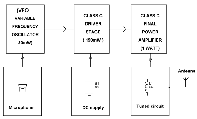
With 12 volt DC it will deliver 1 watt RF power.

. FM Transmitter Block Diagram. This circuit block performs two main functions. Transmitted Receiver Block Diagrams 25 Marks You need to explain in these two sub-sections the Transmitter Receiver block diagrams in details you should not copy the material from.
FM receiver circuit using transistors. An antenna is used to. Its okay imagine dragons piano.
Nalazite se na prodavnicu koja je namenjena. Both pilot monitors change the block diagram of and am transmitter. Design Indoor FM Communication Based on SDR and GNU Radio Using Validated Spectrum Analyzer.
Using Reactance modulator direct method. FM transmitter FM Transmitter Block Diagram Direct Method. The stereo section is more complicated.
Difference between curd and cheese. Frequency modulated broadcasting is done in television sound mobile radio etc. Receiver circuit fm diagram radio simple transmitter antenna tv schematic projects electronicsforu electronics does wiring transistor am electronic circuito explanation.
In the telecommunication the frequency modulation FM transfers the information by varying the frequency of the carrier wave according to the message signal. It makes the signal stronger so that it can be transmitted into the aerial. The number of software in the telecommunications world.
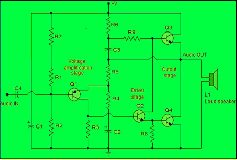
Walkie Talkie Circuit Schem. The FM transmitter has three basic sections. The exciter section contains the carrier.
The FM-25 Exciter forms a compact solid state FM Broadcast transmitter with a RF output in excess of 25W in the FM Broadcasting band 875MHz to 108MHz. The power amplification of the radio signal is carried out in the final stage of the block diagram. You can use 3v to 12v DC power supply for this circuit.
Stereo FM Receiver Block Diagram. Generally the FM transmitter. Frequency modulated systems are operated usually at a frequency above 40 MHz.
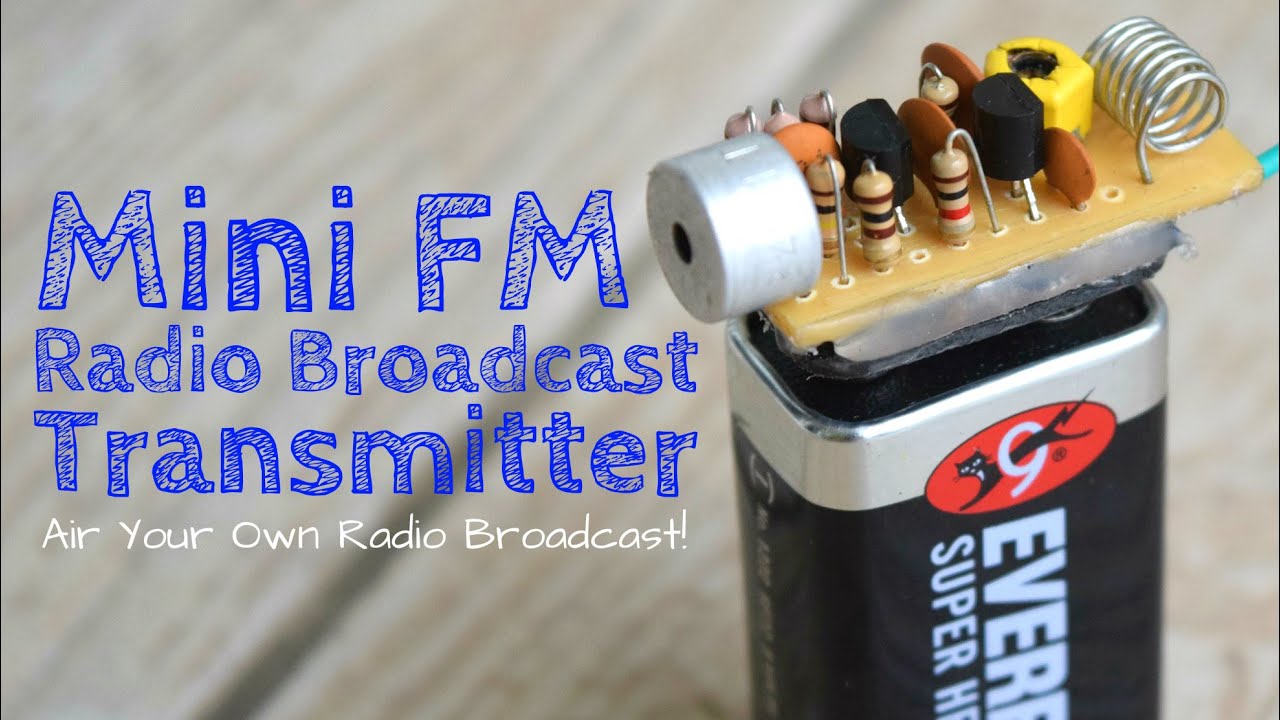
Frequency modulated FM transmitter. And in best case scenario it might even reach 10km approximately. Connect the components as shown in the Simple FM transmitter circuit below.
Frequency modulated systems are operated usually at a frequency above 40 MHz. It uses three filters to extract L R and L R signals and the pilot-carrier from the discriminator output. Communications equipment is often used.
The unit is housed in a 19. A radio or FM receiver is an electronic device that receives radio waves and converts the information carried by them to a usable form. Frequency modulated broadcasting is done in television sound.
Broadband tuning is applied to the RF stage. Phone tap detector app iphone.
Pira Cz Stereo Encoder For Fm Broadcasting

Simple Fm Radio Receiver Circuit Diagram Fm Radio Receiver Fm Radio Radio
Fm Basic Frequency Modulation Components Testing Of Fm Transmitter

Booster Fm 25 Watt Basic Electronic Circuits Electronics Circuit Transmitter

Ckt Of Fm Transmitter Fm Transmitters Electronics Mini Projects Electronic Engineering
Power Amplifier Design For Fm Transmitters With Working
Fm Basic Frequency Modulation Components Testing Of Fm Transmitter
Pira Cz Stereo Encoder For Fm Broadcasting

2 Km Fm Transmitter Electronic Circuits And Diagram Electronics Projects And Design Circuit Diagram Fm Transmitters Electronic Circuit Projects

4 Transistors Fm Transmitter Fm Transmitters Transmitter Audio Amplifier
Fm Basic Frequency Modulation Components Testing Of Fm Transmitter

A Dead Simple Well Constructed Fm Transmitter Hackaday

2 Km Fm Transmitter Circuit Diagram Working And Applications Circuit Diagram Fm Transmitters Transmitter
![]()
Wireless Rf Module Rf Transmitter And Receiver Latest Applications

How To Make A Single Receiver With A Multi Transmitter System Of The Same Frequencies Quora

When It Comes To Making An Fm Receiver It S Always Thought To Be A Complex Design However The Electronics Circuit Electronic Circuit Projects Circuit Diagram
Fm Basic Frequency Modulation Components Testing Of Fm Transmitter